Wednesday, April 24, 2024

CPR St. Marys Station - N Scale Version

CPR St. Marys Station in N-Scale

A Monashee Laser Engineering Kit

A Canadian kit manufacturer.


After having completed this same wonderful kit in HO Scale for Mac, it is now onto the N-scale version he sent my way!


The kit's construction manual states, "If we can draw it. we can make it!"  Love that!  
And...you can make it too!  Heh heh!
This company makes many amazing stations and other structures.
Check out what they offer by copying and pasting their website address below into your computer's browser:
  monasheelaserengineering.ca


In the kit is the packing list that was double-checked before leaving the factory.


Elevation drawings.


Other schematics.


Colour photos of all four sides are shown on one of the sheets.


As I always do, I like to spread the contents across my workbench to verify that all parts are there - and they are!


The first step I undertook was to paint the styrene strips which would form the "drop siding" at the base of each wall.


Because I am painting the drop siding the same red-brick colour as the wooden walls, I first applied a primer coat of black.  
Without the black, the red-brick would appear pink and I don't want that.  
I would then have had to apply numerous coats of red to eliminate the pinkish tones.  
The single undercoat of black was all that was necessary to give me the nice red-brick colour I was looking for.


Because I had just completed the HO scale version of this kit where I had to apply all of the wall shingles using the shingle strips, I noted that the N-scale version had the wall shingles "embossed" already.  
I quickly fired off an e-mail to Rick at Monashee Laser Engineering with a query to verify the fact that I should simply paint over the embossed walls rather than add shingles.  
I was impressed as I received a prompt response from Rick indicating that because the kit is of a smaller scale the embossing was the "way to go".  I agree!  
And it is reassuring to note that if I were to have any further questions they would be answered in an expedient fashion.  
(I doubt that I will have further queries seeing as the construction manual is very well written and covers all aspects of the build in detail.


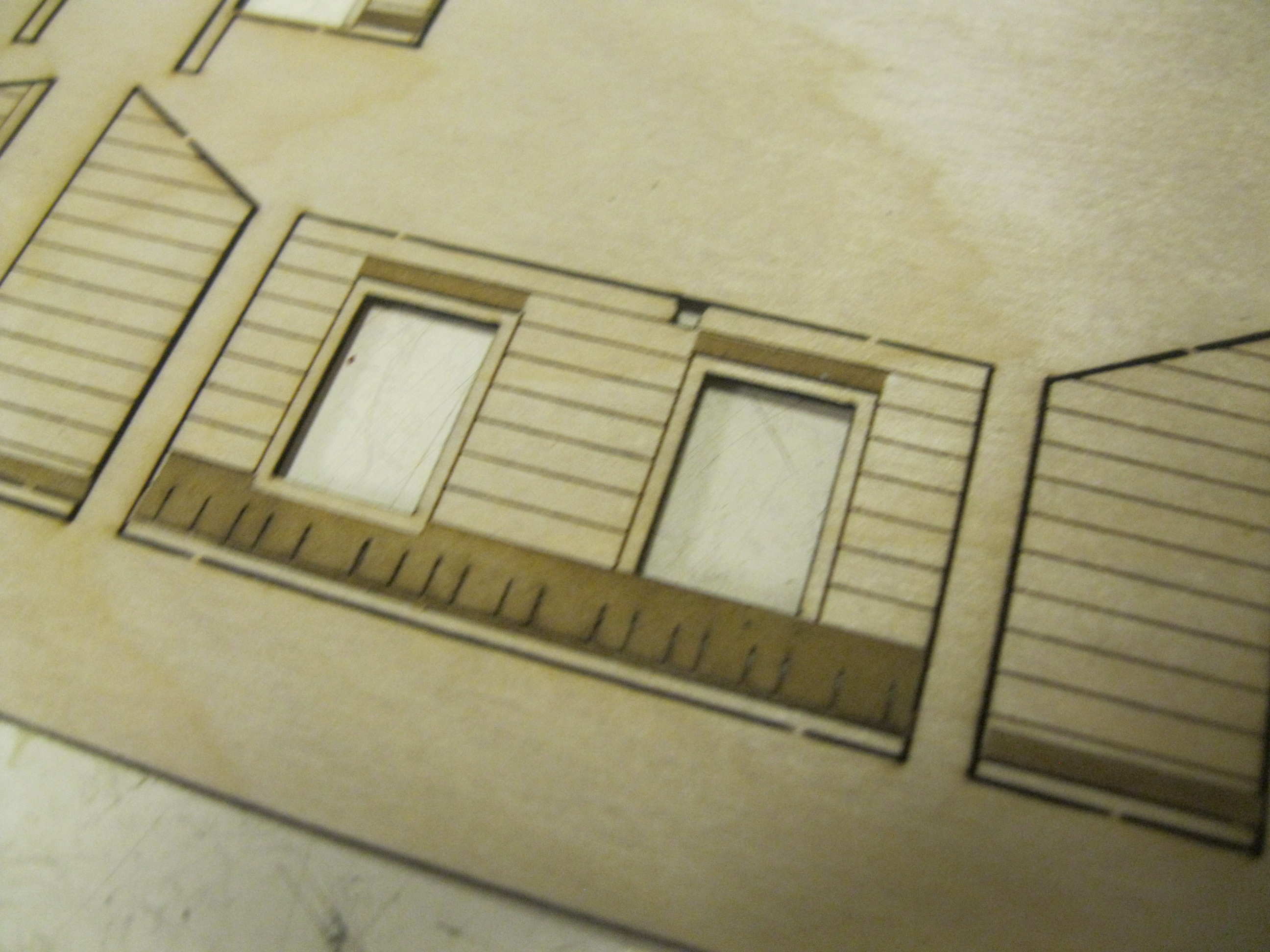
This image shows two sections of drop siding glued in place as well as the embossed wall shingles having been painted.  
I did have to cut the siding a tad more and accidentally nicked some of the paint with the white styrene showing through.  
No problem, a quick touch-up will fix that!  
When I painted the embossed siding I didn't apply a full amount of paint as I did not want any of the darker crevices to fill with paint as I want the viewer to see the distinction between each shingle.
I simply dry-brushed over top.


To do so properly, I first got the paint on my brush and then wiped most of it off in open areas along the side of the sheet off to the right.  Then it was a simple matter of dry-brushing the red brick colour onto the wall shingles.


The painting is coming along nicely.  
Note how I do not worry about "staying within the lines" as these wall sections will be removed from the sheet in short order.  
The upper wall section on the sheet will be glued to the lower wall section.


Door parts are also painted in the red-brick colour.


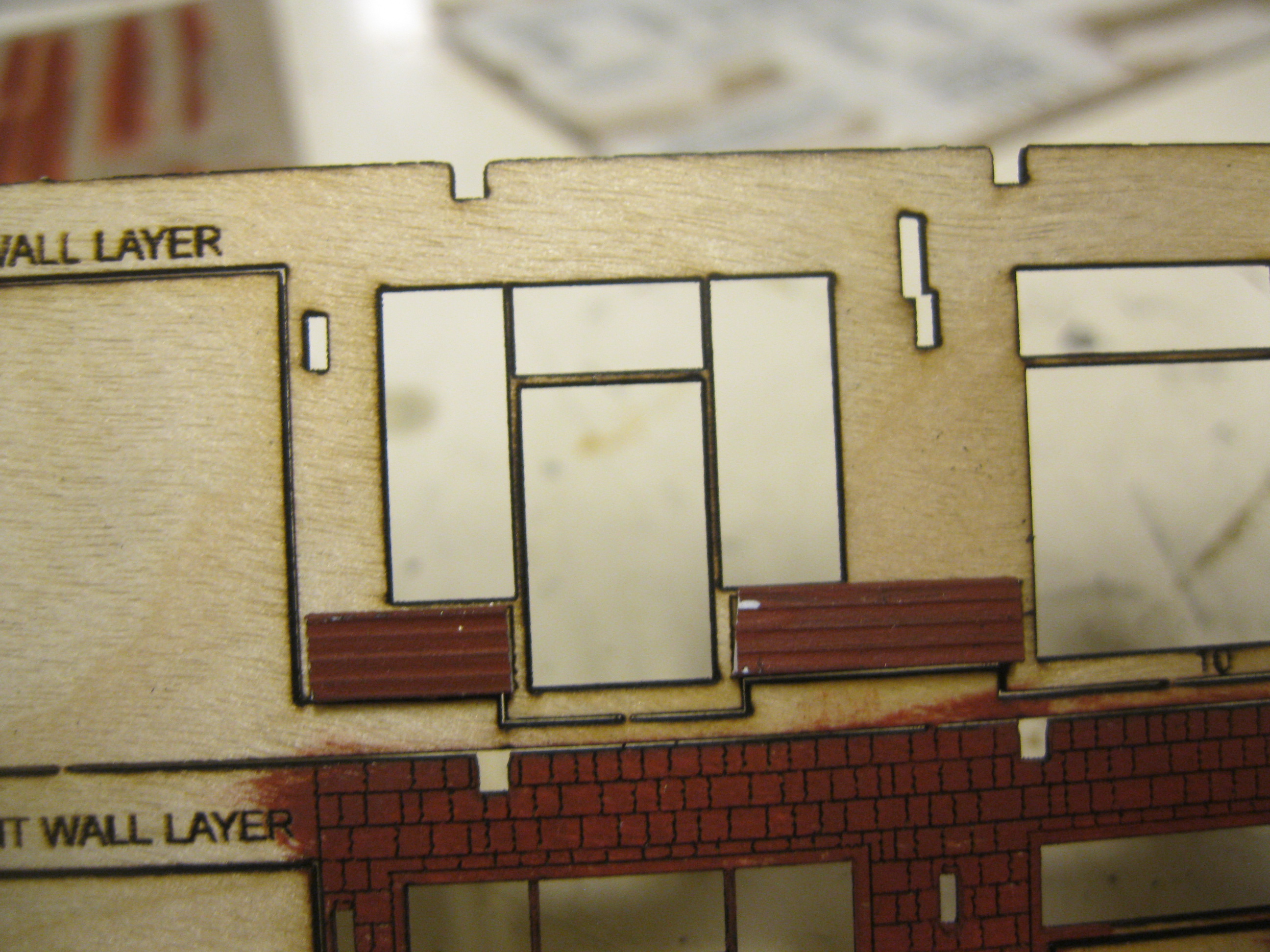
This "overall" look shows the wall areas now painted in their appropriate colours.  The doors remain red-brick, the trim around the doors and window are chocolate brown and the windows with their muntin bars are white.  
Note too how I have already started in on the roof sections up top the image.


For the N-scale version I will be painting the trim the chocolate brown colour as per the appearance of the station on the box cover and in the instructions. 
 In Rick's HO manual  he explained that depending on the station or depending on the year or era, the trim and roof support brackets could appear in either the white/cream colour or a dark chocolate brown.  
For me as the modeler, it will be fun to deviate slightly between the two stations realizing that both are painted in a realistic fashion!  Big smile!


Here you see the very tiny N-scale windows have now had their paper backing removed to expose the adhesive side which I have pressed on top of their designated window glazing.


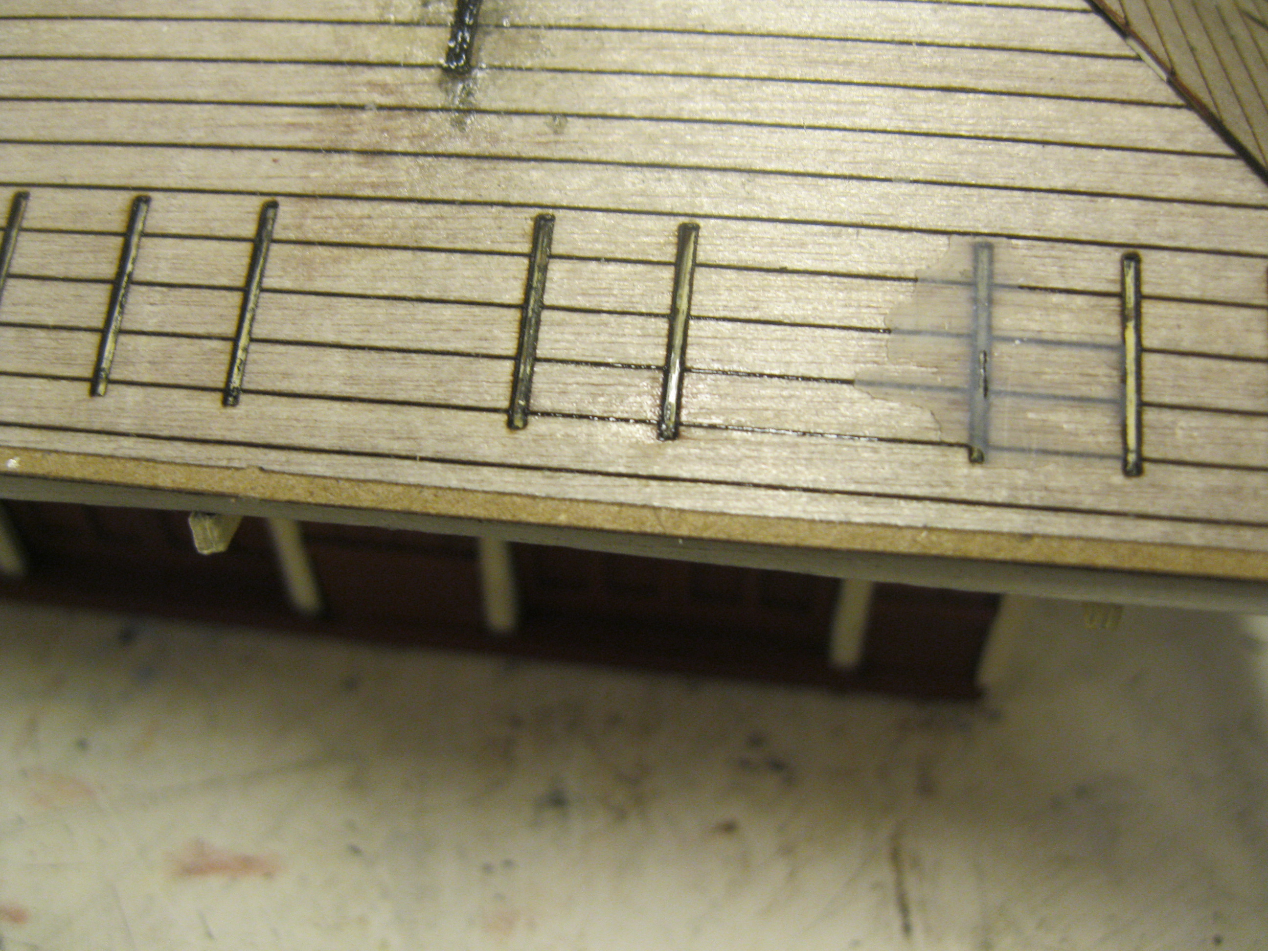
The right side wall now has the trim and windows adhered along with the drop siding and the siding cap trim.  The windows are lined up perfectly.  
You don't see the bottom of the white muntin bars due to the angle I snapped the shot to avoid my shadow covering the wall section.
Remember, all the wall sections are two walls which the modeler glues together.


Time to take on the rear wall.  The chocolate brown trim is now in place.


Here comes the tedious part...the windows.  
When I say tedious, I mean repetitious and time-consuming.  Tedious parts mean that the kit is a highly detailed one of excellent quality allowing the modeler more steps in order to achieve an superb model!


The little leftover paper scraps from the windows' paper backing.


Some sanding is required with a few passes on the light sandpaper.


Coming together nicely!  Yes, some paint touch-up will be required and I have yet to apply the siding cap trim between the shingled wall and the lower drop siding.


One area of the rear wall is done...on to the next!


The full rear wall "sans extension" is complete with the doors and siding cap trim in place.  
And, you may think that building an HO scale craftsman kit is as tricky as neurosurgery - well, in N-scale you can keep the neurosurgery description and add "rocket science".  Just kidding everyone!  
These kits go together beautifully and if anyone takes their time and follows the instructions, they should be able to complete on of these wonderful kits in any scale!


While these kits go together like a jigsaw puzzle, sometimes a bit of sanding or filing is recommended by the kit manufacturer.  I encountered this when it came time to glue the wall structure to the base.


While there are still additional details to be added, the wall fits into the base beautifully for this "test-fit"!


With the completed rear wall up top, it is time to add the windows to the front wall seen below.


Done!  Of course it didn't take the five seconds it took me to add this image!  Big smile!


The backside of the two laminated wall sections.


All the walls are complete.


The base for the station has all the appropriate slots to marry with the tabs located on the bottom of the walls.


These are the interior walls.  You would paint or decorated them if you wanted to purchase additional interior detailing to add an interior.


Even though we are not going to detail the interior, I glue them in to add support as some of their tabs will go into slots on the various walls to add support.


The tab and slot design is wonderful!


The rear wall with the rear wall extension sub structure in place.


Looking good!


Remember...this is N-scale.  Check out the amazing detail!  Some touch-ups are still waiting to be done.


A view from above.


I've glued in some black construction paper so that it will appear "dark" when you look through the windows into the building rather than an "empty" station with no furniture and no inside details.


Another view from above.


Hey!  Check out the size difference between the N and HO versions of the kit.
(Can you tell which one is N?)
  Couldn't resist!  Big grin!


Yet another drone shot!


Here I am...Mike Hamer - playing his Hamer guitar!
  In behind me are two other model railroaders/musicians....Chris Lyon in black and Chris Savage in white.
I will continue to add to this posting as the kit progresses!
Stay safe and stay healthy!
Mike Hamer, Ottawa, Ontario, Canada

Monday, April 15, 2024

Canadian Pacific Railway St. Mary's Station - HO Version

Canadian Pacific Railway

St. Mary's Station

Monashee Laser Engineering

You can enlarge the images by clicking on them and return to the default look of the page by clicking outside them.

I've been asked to build the Canadian Pacific Railway's St. Mary's Station in both HO and N scale for a couple of gentlemen who live in southern Ontario.


I'll begin with the HO version first.


The laser cut kit is from Monashee Laser Engineering.  The packaging is excellent as is the construction manual.


All good kit manufacturers include a packing list.  
This one has been check-listed from the factory and no parts are missing.


As always I like to splay out the various components of the kit before beginning the build.


The laser art technology of today is exceptional.


All sheets are carefully labelled so there is no confusion as to which parts go where.


The drop siding which forms the bottom area of each wall section is made from styrene.
Note the long white styrene strip I have placed across the upper wall section.


Before cutting, I make a mark with my pencil.


Et voila!  A perfect fit.


I always begin a new project with a fresh razor blade.


Some sanding is required to bring the siding to the desired length.


I have placed the drop siding where it belongs on a temporary basis for this image.


These wall sections I have been showing are the inner wall.  They will eventually be adhered to outer wall sections making for a strong bond.


For fun I decide to place these unfinished inner walls up to see how things will appear.


Slots in the inner floor base accommodate these sections.
This image was taken under different lighting conditions.


Yes, this certainly will be a lovely station!


Again, under differing lighting.


I have painted the drop siding the brick-red colour that the main station walls will eventually wear.  
I had to first prime these small styrene sections in black to ensure the red-brick colour will match the eventual colour of the shingled sides.  
This was necessary as painting red over the white styrene would result in a more pinkish hue that would not match the rest of the painted wooden shingled walls.  
Crazy Glue works well when adhering styrene to wood.


All drop siding sections are now in place.


Another look on my carpeted floor.


Time to begin shingling the outer wall.  
Here I am placing the "First Shingle Started Strip".
My sharp razor will make the necessary cuts.


Here is where the time-consuming part comes in.  
With the sharp blade I have to cut around the window frame area.  
Notice how I have already done this to the left window but not the right one.  


Similar treatments happen up top as well.  This takes time and care to detail.


Some further trimming will take place when I go to test fit the window frames.


Note how a starter strip is necessary above the window and door openings.


Some of the narrower wall areas requiring shingling are tedious as well, but the sharp blade makes the cutting happen rather easily!


The instructions show where the starter strips and first shingle rows are placed.  They also indicate the areas where trimming is needed.


All the shingles are in place and all that is left here is to finish trimming the upper left area.


Time to marry the two wall section parts together.  
This image was shown previously.


These left and right wall segments will combine into one.


Let's perform another "test fit".

\

Looking good so far!
The upper shingles will eventually be painted the same red-brick colour as the lower drop siding.
Note where some shingled areas have slotted openings.  These slots will accommodate the tabs on the brackets holding the roof.


To adhere the two parts of each wall section I will use carpenters glue.


With the glue applied I will carefully align the two pieces.


This image shows the test fit which I have not pressed in place as of yet.


Time to apply the glue.


The two sections are adhered to each other.


My trusty weights will ensure the walls remain in place as the glue sets.


The shingles have now been painted in the same brick-red colour of the lower trim.


I painted the rafter tails and window sill trim an off-white called Tapioca.


More of the trim appears on the bottom half of the sheet above painted in the tapioca colour.  The window frames and muntin bars are painted in an antique white colour.


Close up view of the windows.


Close up view of the frames.


The above sections make up the exterior doors painted in the red tones.


I used a "Colonial" furniture stain to colour the interior doors.


Here's the look under differing lighting.


One wall section is nearing completion.  The tabs are for the roof supports and some additional trim and window sills will have to be glued to the wall section.


Let's examine how the windows work within the context of the kit instructions.  Each window uses "peel & stick" technology.  Note the window atop the acetate glass on the upper left with the muntin bars.  I have started to remove the covering to allow the frame to stick to the imitation glass surface.


All glass for the windows is labelled specifically for each window location.


In order to fit within the framework of the window opening, some sanding is required.


A few swipes across the Garnet sandpaper over all four sides will do the trick.  I will be conducting this procedure with all window frames.


These are now adhered to the glass surface after I removed the backing to allow the sticky surface to attach to the clear acetate.


The upper windows are in.


The upper section of the right lower part is in.


The bottom window is now in.


The lower row shows the walls with their shingles in and painted.  The middle row shows the frames in around the window openings.  The upper row shows four walls with all windows in.


The frame is now adhered to the shorter walls that lead to the front bay window.


The trim strip separating the lower wall section known as the "drop siding" from the shingled area is glued in place on the left wall.


The trim strip finds itself on the right wall.


The doors are now made...again using the peel and stick methodology.  They are in place along the front wall.


Interior walls are provided, although we are not decorating the interior for this build.


The supports for the rear extension now appear.


I've placed black construction paper so that you cannot see into an unfinished interior.


A look from above.


The walls all mate perfectly thanks to the "tab in slot" construction.


An aerial view with all four walls in place.


I have temporarily placed the roof support panel atop the station.


Under different lighting.


Let's check back in on that rear wall extension.


One wall is glued in place.  Note the slots in the bare wall and on the floor to accommodate the tabs.


All three walls are now in but we have yet to add the trim in the corners.


I have added glue along the base which will allow me to adhere the "splash board skirting" to the lower area.


You can now see the skirting along the base of all walls.


A look with the platform support.


My next job will be tackling the roof and then I'll finish the project when I finally get to layering planks atop the platform.


A low angle view of the project thus far.


The next step is to remove the roof beam support brackets from their sheet and paint them. 


I ensured the roof supports were well seated and lined up 90 degrees to the wall.


The front wall is done. 


Then it was on to the roof section itself.  
The instructions tell the modeler to elevate the ceiling plate to accommodate the rafters which have their ends protrude lower than the plate itself. 


The rafters as seen on their sheet.


Literally five minutes later they were in place.  
No need to worry about the appearance of the glue in the corners as this area will be hidden by the roof over top - although I did clean up the excess glue anyway!  Big smile! 


The modeler has the option of making the roof removeable, but since we are not going to the great length and expense to purchase the various interior detailing, I simply glued the roof in place.


The ends of the rafters fit perfectly into the slots at the top of the walls. 


As seen under different lighting.


Time to adhere the 6x6 stripwood support beams.  The instructions indicate to use the supplied templated to cut the beams to length. 


The rafter tails begin going in. 


This is a step that some modelers choose to skip because rarely will the viewer see the rafter tails anyway.  I chose to add them in order to make the model complete.


One roof section is test-fitted and everything goes together beautifully.


An under-eaves look at what you most likely will not see when the model is placed on the layout.


The smudge marks on the roof are where I used glue and spread it over top the slot areas once the tabs were put in place.  The gap between the end roof sections and the front is supposed to be there.  It will be covered by the shingles.


Now for the very time-consuming aspect of the job.  Applying the shingles.  Here they are seen on their sheet.


Note the shiny appearance on their underside.  This is the side with the glue that will be used once you peel the top paper off the shingle strips.


Narrow starter strips come on the sheet as well.  They are six scale inches wide.


I begin by placing a starter strip at the base of each roof section.


Then it is a simple (yet time-consuming) job of cutting the strips using a very sharp razor blade to peel the protective layer off each length and then applying them to the roof using the pre-scribed lines as a guide.


Note how I have to trim the ends of each row at an angle to match the angled joint where the two roof sections meet.


The front roof is done!


Now to the back roof.  Note the square where the chimney will be glued to the roof.


Once again, a sharp razor blade is used to cut away a portion of the shingle strip in order to keep the chimney's square visible.


I also added a starter strip at the top of the square before using my razor blade again to cut away the section of the upper strip in order to once again reveal the full square for the chimney.  Not quite neurosurgery...but almost!  Big grin!


Looking good.


For the end roof, I began by creating an angled cut for the far end of the strip and leaving some excess length available at the near end which you see jutting out.


Then it is a simple matter of using scissors to make the cut.


Again, we don't worry about the irregular look of the line which acts as the border between the two roof sections because shingle hip caps will cover the line.


Here is the sheet of the shingle hip caps.


You have two alternatives when covering the seems between the roof sections.  You can take a sheet of paper, fold it in half and make a narrow cut to create a single lengthy roof hip cap...or you can take the more tedious method of installing the single caps one at a time.  I chose the latter as I felt it was the better alternative seeing as the sheet of the squares was provided with the kit.


Next step - the ridge along the lengthy front and rear wall sections.


This was very time-consuming as well due to the fact that these square caps were not self-adhesive.  I had to apply glue to each one.  
By using the term "time consuming" I am not being negative - I'm being realistic.  Sometimes it's these more mundane steps in a craftsman structure's build that truly make the model the great one it is and will be!  Big smile!


Then it was on to the chimney.


I painted the bricks red.  I will add a second coat.  I will leave the mortar a darker colour as mortar comes in a wide variety of colours and tones. 


The cap is painted a concrete colour and the flashing is aluminum.  The roof has been painted a flat black.


We're almost done, but we still have the station platform to build.  I first stain the stripwood with SAMAN Golden Wheat furniture stain.


I then apply a wash of black acrylic.


These sticks will make up the planking for the platform.


I am sanding the front edge of the platform base as I wish to apply a wash to that area as well.  
The sanding eliminates the burn marks which result from the laser cutting technique.


I have cut the planking to lengths and now use my trusty square to ensure the planks are...well...square!  Heh heh!


Because I stained the stripwood individually, the result is the varied look to each plank which adds character.


I will apply a wash of acrylic black over top the full platform once it is complete to tie in the various tones to create a somewhat uniform look.


The underside of the platform.


Time to photograph the finished product!
These next three shots were taken with my incandescent work lamp focused on the structure.


The St. Marys Station is a beauty for sure!


I would travel here to catch a train!


I have now turned off my workbench lamp as these next three images were taken with my regular fluorescent overhead lights in my work area.


This kit was a joy to build.


The Monashee Laser Engineering group did a fabulous job in creating this station.


Apologies to our CP fans out there, but I don't have Canadian Pacific passenger equipment...only cars for the Boston & Maine!  Big grin!


The car colour matches the station perfectly! 


Quite complementary, for sure!


Under the overhead lighting.


Looking really nice! 


"All aboard!" 


Mac & Mike may very well be on board this passenger train!


Here we see our B&M power!


No light on the locomotive as the track is a dummy track and not powered.


Aha!  Maine Central power visits the station!


Lovely!


An overall glance at "Where the action takes place!"  Heh Heh!
We see Mike's work lamp.


Same image without the lamp!


Hey, here I am a few years ago hard at work at the workbench!
Thanks go out to Mac for asking me to take on this build of the St. Marys Station in HO scale.  
Mac also sent along the same station in N-scale, so that will be my next project which I am really looking forward to get underway with.
Have a wonderful week everyone!
Mike Hamer, Ottawa, Ontario, Canada